High Density Polyethylene (HDPE)
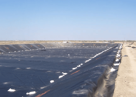
High Density Polyethylene (HDPE) is the most common field fabricated geomembrane material from reservoirs and lagoons to municipal water ponds.
Features
-
- Durable, UV stable material
- Supplied in 22.5 ft (6.86m) wide rolls
- Excellent chemical resistance
- White surface available by special order
- Conductive layer available by special order
Applications
-
- Excellent long term exposed lining material
- Landfill liners
- Heap leach and mine ponds
- All water containment applications
High Density Polyethylene (HDPE) Specifications
×
Product Description
High Density Polyethylene (HDPE) popularity is primarily due to its low initial material cost and excellent UV & chemical resistance. This allows thicker sections of HDPE to be used in exposed applications where the cost of other materials may be prohibitive. HDPE is a versatile material that is used widely across many applications. One of the primary uses of HDPE is as a liner at the base of landfills, where its chemical resistance is put to use. HDPE applications also include pond linings and water containment projects. HDPE is a field assembled lining material that cannot be practically fabricated in the shop. Therefore, all HDPE projects, regardless of size, must be installed by trained installers.
Product Details Specifications Project Profiles Tech Notes Drawings Brochures
-
Product Details
Additional details for this product are listed below. Scroll down to view all product content. Select the other tabs to see additional resources related to this product.
Print Cut Sheet Contact Our Experts
14 April 2021 HDPE Minimum Material Properties, Black Style ASTM HDPE 40 Smooth HDPE 60 Smooth HDPE 80 Smooth HDPE 40 Textured HDPE 60 Textured HDPE 80 Textured Nominal Thickness D5199 40 mil 1.0 mm 60 mil 1.5 mm 80 mil 2.0 mm 38 mil 0.96 mm 57 mil 1.45 mm 76 mil 1.90 mm Asperity Height D7466 16 mil 0.4 mm 16 mil 0.4 mm 16 mil 0.4 mm Density D792 > 0.94 mg/l > 0.94 mg/l > 0.94 mg/l > 0.94 mg/l > 0.94 mg/l > 0.94 mg/l Tensile Strength Type IV Die D6693 Yield Strength 84 ppi 15 kN/m 126 ppi 22 kN/m 168 ppi 29 kN/m 84 ppi 15 kN/m 126 ppi 22 kN/m 168 ppi 29 kN/m Break Strength 152 ppi 27 kN/m 228 ppi 40 kN/m 304 ppi 53 kN/m 60 ppi 10 kN/m 90 ppi 16 kN/m 120 ppi 21 kN/m Yield Elongation 33 mm Gauge Length 12% 12% 12% 12% 12% 12% Break Elongation 50 mm Gauge Length 700% 700% 700% 100% 100% 100% Tear Resistance D1004 28 lbs 125 N 42 lbs 187 N 56 lbs 249 N 28 lbs 125 N 42 lbs 187 N 56 lbs 249 N Stress Cracking D5397 500 Hours 500 Hours 500 Hours 500 Hours 500 Hours 500 Hours Puncture Resistance D4833 72 lbs 320 N 108 lbs 480 N 144 lbs 640 N 60 lbs 267 N 90 lbs 400 N 120 lbs 534 N Carbon Black Content D6370 2.0-3.0 % 2.0-3.0 % 2.0-3.0 % 2.0-3.0 % 2.0-3.0 % 2.0-3.0 % Carbon Black Dispersion D5596 Cat 1 or 2 Cat 1 or 2 Cat 1 or 2 Cat 1 or 2 Cat 1 or 2 Cat 1 or 2 HPOIT D5885 400 mins 400 mins 400 mins 400 mins 400 mins 400 mins Oven aging at 85º C HPOIT – % retained after 90 days D5721 D5885 80% 80% 80% 80% 80% 80% UV Resistance High Pressure OIT (min. ave.)- % retained after 90 days D7238 D5885 50% 50% 50% 50% 50% 50% Maximum Continuous use Temperature1 60°C 60°C 60°C 60°C 60°C 60°C 1Please contact Layfield Technical Services for more information
14 April 2021 HDPE Minimum Field Seam Strengths Style ASTM D6392 HDPE 40 Smooth HDPE 60 Smooth HDPE 80 Smooth HDPE 40 Textured HDPE 60 Textured HDPE 80 Textured Bonded Seam Strength Test Temp 23°C, 73°F 25.4 mm (1″) Strip 80 ppi 14 N/mm 120 ppi 21 N/mm 160 ppi 28 N/mm 120 ppi 21 N/mm 120 ppi 21 N/mm 160 ppi 28 N/mm Peel Adhesion Strength (Extrusion Welds) 25.4 mm (1″) Strip 52 ppi 9 N/mm 78 ppi 14 N/mm 104 ppi 18 N/mm 78 ppi 14 N/mm 78 ppi 14 N/mm 104 ppi 18 N/mm -
Specifications
Available detailed drop-in specifications for this product are linked below. For drop-in specifications on other products please go to the appropriate product page or look in the Resources menu.
Cut Sheet
High Density Polyethylene (HDPE) is the most common field fabricated geomembrane material from reservoirs and lagoons to municipal water ponds.
HDPE BioGas Cover CSI Specification (33 47 16.13)
HDPE Full Specification
Insulated Cover CSI Specification (33 47 16.13)
-
Project Profiles
Below are links to project profiles related to this particular product. For project profiles on other products please go to the appropriate product page or look in the Resources menu.
Enviro Liner & Arctic Liner – In-situ Oilsands Operation
LOCATION: Fort McMurray, Alberta TIMEFRAME: July, 2002 PRODUCT: Enviro Liner®, Arctic Liner®, HDPE PROJECT PARTNERS: Owner: SuncorInstaller: Layfield
Featured Products in this Project Profile EnviroLiner Product Page Nonwoven GeotextilesProduct Page
Geoterra- Sulpher Block Walkway
LOCATION: Cremona, AB TIMEFRAME: Spring 2009 PRODUCT: GEOTERRA, LP16 Non-Woven Geotextile, Smooth HDPE 60 mil PROJECT PARTNERS: Owner: Shell Canada Energy Installation: Layfield
Featured Products in this Project Profile Non-Woven Geotextile Product Page Smooth HDPE Product Page
Geosynthetic Containment System – Concrete Cover
LOCATION: West of Conklin, AB TIMEFRAME: April – November 2009 SCOPE OF WORK: Earthworks, survey, piping, geosynthetic containment system, concrete cover PROJECT PARTNERS Owner: Statoil Prime Contractor: IMV Construction General Contractor: Layfield
Featured Products in this Project Profile HDPE Geomembrane Liner Product Page LP8E Non-Woven Geotextile Product Page
HDPE 80 mil Floating Covers – CCD Tank
LOCATION: Key Lake, Saskatchewan TIMEFRAME: Fall 2011 – Spring 2012 SCOPE OF WORK: Design of Floating Cover over CCD Tank PROJECT PARTNERS Cameco Corp MDH Engineering Saskachewan Red Engineering Edmonton North West Hydraulic Consultants (NHC)
Featured Products in this Project Profile Modular Insulated Cover Product Page HDPE GeomembraneProduct Page
Floating Cover – Cargill Anaerobic Cover
LOCATION: High River, AB TIMEFRAME: Summer 2004 SCOPE OF WORK: Design & install anaerobic floating cover system with anchor system and gas collection piping. PROJECT PARTNERS: Owners: Cargill Foods
Featured Products in this Project Profile Anaerobic Floating Cover Product Page
HDPE StudLiner
LOCATION: Foster Creek, AB SCOPE OF WORK: Provide 80 mil HDPE Studliner for primary & secondary containment of mud storage cells PROJECT PARTNERS Owner: EnCana Oil & Gas Partnership Supplier: Layfield
Featured Products in this Project Profile HDPE Studliner Product Page
Cargill Foods – Biogas Food Processor
Location: High River, Alberta Timeframe: 2003 Scope of Work: Engineering design, Supply and Installation of anaerobic floating cover system Project Partners: Owner: Cargill Foods
Featured Products in this Project Profile Anaerobic Floating Cover Product Page
Geomembrane waterproofing for a 10-mile wooden flume
LOCATION: Washington State TIMEFRAME: 2015 SCOPE OF WORK: The project also required the installation of 165,000m² (1,775,400ft²) of high-strength geotextile under the geomembrane to help structurally reinforcet he deteriorating wood flume. PROJECT PARTNERS: Layfield – Installation and Supply
Featured Products in this Project Profile High Strength Geotextiles Product Page
-
Tech Notes
These tech notes have been selected as being the most appropriate for this product. For a listing of all tech notes please see the Resources menu.
Metric Conversions
Pond Volume Calculator
Cold Temp Handling Guide
Although it is preferable to avoid installing lining materials in cold temperatures, occasionally it can not be avoided. Cold weather usually requires a modification of installation techniques, or may involve substitution of materials to ones which have superior cold weather handling capabilities.
Ph Resistance
Chemical Resistance
Wedge Welding
Extrusion Welding
Subgrade Preparation
Chem Field Testing
UV Resistance
Chem Resistance Charts
Backfilling Geomembranes
Geomembrane Slack
-
Drawings
These drawings have been selected as being the most appropriate for this product. To see all available drawings please see the Resources menu.
Angle Bar Attachment 1
Angle Bar Attachment 1
An angle bar attachment is a standard attachment to concrete. The angle bar provides stiffness so that a compression seal can be made with the liner and gaskets. Angle bar can be attached at 300 mm (12″) centers which is more cost effective than the 150 mm (6″) centers required for flat bar.
Liners are attached to clean, smooth concrete, using wedge anchors drilled into place. These wedge anchors are best placed during liner installation as it is very difficult to keep the concrete surface clean and smooth with cast-in-place anchors. The most difficult aspect of attaching liners to concrete is to obtain a smooth, clean surface.
To download this component file as an AutoCAD drawing, please click the link below.
Angle Bar Attachment 1
To download this component file as a PDF document, please click the link below.
Angle Bar Attachment 1(PDF)
×
Exposed Vent Detail
Exposed Vent Detail
In certain circumstances gases can accumulate under a geomembrane and cause uplift. A gas venting system can prevent damage to the liner when uplift is predicted. A geo-net or geotextile vent layer is provided under the liner and up the slopes. At the top of the slopes a vent is provided to allow the gas to escape to atmosphere. The detail in this drawing shows a typical gas vent at the top of a slope in an exposed geomembrane. A drawing for a backfilled geomembrane vent is also available.
To download this component file as an AutoCAD drawing, please click the link below.
Exposed Vent Detail
To download this component file as a PDF document, please click the link below.
Exposed Vent Detail
×
Flat Bar Attachment 1
Flat Bar Attachment 1
A flat bar attachment is used when a low overall height is required, usually when the attachment is to be capped. Flat bar is also used to go around curves. Layfield normally uses an angle bar attachment for most work. Flat bar does not provide sufficient stiffness to make a permanent compression seal. Sponge neoprene gaskets, often specified with flat bar, do not normally provide long term compression. Usually only 50 to 60 durometer neoprene gaskets should be used. Flat bar is attached at 150 mm (6″) centers which normally costs more than the 300 mm (12″) centers required for angle bar.
Liners are attached to clean, smooth concrete, using wedge anchors drilled into place. These wedge anchors are best placed during liner installation as it is very difficult to keep the concrete surface clean and smooth with cast-in-place anchors. The most difficult aspect of attaching liners to concrete is to obtain a smooth, clean surface.
To download this component file as an AutoCAD drawing, please click the link below.
Flat Bar Attachment 1
To download this component file as a PDF document, please click the link below.
Flat Bar Attachment 1
×
Backfilled Vent Detail
Backfilled Vent Detail
In certain circumstances gases can accumulate under a geomembrane and cause uplift. A gas venting system can prevent damage to the liner when uplift is predicted. A geo-net or geotextile vent layer is provided under the liner and up the slopes. At the top of the slopes a vent is provided to allow the gas to escape to atmosphere. The detail in this drawing shows a typical gas vent at the top of a slope in a backfilled geomembrane. A drawing for an exposed geomembrane vent is also available.
To download this component file as an AutoCAD drawing, please click the link below.
Backfilled Vent Detail
To download this component file as a PDF document, please click the link below.
Backfilled Vent Detail
×
-
Brochures
These brochures have been selected as being the most appropriate for this product. To view all brochures please see the Resources menu.
Recently Viewed/Related Products
-
Enviro Liner 4000® – Geomembrane
amazingcarousel.com
Enviro Liner 4000 is Layfield’s line of LLDPE flexible geomembranes.
-
Enviro Liner 6000 – Geomembrane
Enviro Liner® 6000 is Layfield’s flagship flexible geomembrane liner with exceptional UV resistance and performance properties.
-
Installation and Construction Services
Layfield is a skilled installer of all geosynthetics products from geomembranes to floating covers to wick drains.
-
Leak Location
The Electrical Leak Location method is a proven technique for finding defects in completed lining systems for repairs, maintenance, or as part of QA testing.
-
Nonwoven Geotextiles
Nonwoven needle-punched geotextiles offer excellent water flow properties for drainage and other applications.