+86-159 9860 6917
info@geofantex.com
geofantex@gmail.com
+86-400-8266163-44899
By Ian D. Peggs – When asked what voltage setting was used to perform spark testing on a pipe penetration weld, the operator said “Dunno, I just turned it to the max as stated in the instructions”! This is just the right way to miss leaks, as happened. So, let’s look at what is occurring during geomembrane spark testing. In awkward places in geomembrane liners, such as at pipe/flange welds and underneath pipe boots, where extrusion welds cannot be vacuum box tested to meet QC and CQA requirements, a practical, and under-appreciated, solution is to perform spark testing. There are two types of spark testing – AC and DC. Both require the placement of a conductive wire at the edge of the top sheet. While the DC method produces the more reliable results the AC method is more frequently used. ASTM D6365 describes the DC method in which the copper wire is grounded or lead directly to the negative terminal of the power supply. This is not required in the AC method. In both cases a positive search electrode (brass brush or single tip probe) is passed along, and in contact with, the weld bead. In the DC method a potential is applied between the power supply electrodes of a magnitude that will discharge across an air gap or through an air passage in the weld of a specific distance. The relationship between applied potential and air gap is: V = K (t)0.5
| Where: | |
| V = voltage t = thickness or air passage length K = 7900 when t in mm K = 1250 when t in mil (0.001 in.) |
Figure 1. Potential leak path lengths. Table 1. Voltages required for specific air path lengths
| Distance (mil) | Distance (mm) | Voltage (kV) |
| 40 | 1 | 8 |
| 60 | 1.5 | 9.5 |
| 80 | 2 | 11 |
| 100 | 2.5 | 12.5 |
| 250 | 6 | 20 |
| 375 | 10 | 25 |
| 750 | 19 | 35 |
However, at the same time, the voltage must not be so high that it will punch a hole through the geomembrane thickness. At a dielectric constant of 600 V/0.001 in. (mil) for HDPE these excessive voltages are:
| 40 mil | 24 kV |
| 60 mil | 36 kV |
| 80 mil | 48 kV |
| 100 mil | 60 kV |
The AC method also requires a wire in the weld bead but there is no need to ground it; there simply needs to be a highly conductive medium behind the weld that will indicate a penetrating air passage. In some cases there is a conductive medium, such as wet soil, GCL, or concrete directly under the liner but at welds it must be assured that this medium is directly behind the weld (at the edge of the top sheet) and not some distance away at the edge of the sheet overlap – a distance that will significantly increase the spark discharge distance. Therefore, the geomembrane overlap in Figure 2 cannot be tested without a wire, while the butt fillet weld could. However, it is best practice to always install the wire.
Figure 2. Long path to ground in geomembrane seam (top). Shorter path to ground in thick plate butt weld (bottom). The wire should be in the “same” geometrical position along the full length of the weld. Theoretically, the optimum position is just under the edge of the top sheet as shown in Figure 3. If placed along the edge of the top sheet (Figure 4) it could interfere with the ability of the weld extrudate to flow into the corner and to bond to the edge of the top sheet. This is the same reason why the top edge of the top sheet is beveled – to better ensure that extrudate will bond with the edge of the top sheet, thereby avoiding a vertical crack-type defect that could propagate upwards through the weld bead if the weld is stressed.
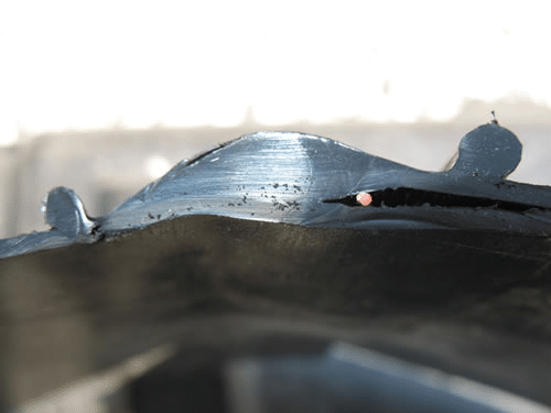
Figure 3. Wire placed under edge of top sheet.
Figure 4. Possible crack-type defect (arrowed) with wire at edge of top sheet. Recognizing that the air passage length is critical for the identification of potential leaks it is important to recognize the pros and cons of using single point or brush-type search electrodes. When passed along a weld a single point electrode may or may not detect a leak dependant on whether the electrode is passed directly over the entrance to the longest calibrated leak or whether it is passed on the other side of the bead away from the entrance to the leak. In the first case the leak will be detected, in the second case it will not. However, if the weld is re-surveyed the reverse may occur! Thus a re-survey after some leaks have been repaired may find additional leaks that were not found in the first survey. Therefore, a brass brush electrode that exceeds the width of the extrusion bead will more assuredly find all leaks in the first pass. In many containment situations a weld spark survey will be done on completion of the liner but before the basin is filled with water for hydrostatic testing. Following a water test the basin may then be filled with operating process solution. Frequently, when hydrostatically tested, pre-tested welds are found still to be leaking. The basin is emptied and spark testing performed again. Often this confirms additional leaks in the welds. These may or may not be new leaks resulting from stressing the liner under operating loads. However, pre-existing leaks that were too long for spark detection will now be filled with water which, being more electrically conductive than air, will make them detectable in the spark test. A similar situation may occur if the operating process solution is more conductive than water. Therefore, in such cases it may not be the technique or the operator that is performing inadequately, it is just a characteristic of the technology. However, the possibility of new leak as a result of loading the liner still exists. In a recent project the wire behind a pipe penetration flange was used as the ground electrode for a water lance survey. When the water contacted the weld bead tucked under the pipe (a difficult location to weld effectively, Figures 5 and 6) a strong leak signal was generated over about 6 in. of weld bead.
Figure 6. …often being done by manually pushing blobs of extrudate into place. A single-probe AC spark tester was used to more accurately locate the leak. The spark test produced one spark about 2 in. from the right end of this region, on the outer edge of the weld. This area was repaired. A second water lance survey generated another signal about 2 in. from the left end of the original bead on the inner edge of the bead. Thus, water penetration was able to identify a leak that the spark test did not. The spark would not discharge along the long passageway. The second leak location was repaired and a third water lance survey was performed. It gave no signal. The weld was acceptable. As a side observation this was a weld that the installer was initially intending not to vacuum box or spark test. In summary, when spark testing or specifying spark testing, determine the maximum length of air passage that you want to detect, set the voltage accordingly, calibrate to ensure the spark will, in fact, discharge across this gap, and use a brush electrode that will contact all of the surface of the weld bead. Or, if using a pointed probe, ensure it is, at least, passed along the center and along each edge of the weld bead, depending on the size of the bead and the voltage setting. The spark test has a very significant role to play in liner weld testing – but only if it is understood.
Geomembrane Seam Spark Testing; One Step Further
Where is the most detailed extrusion welding work in any containment facility? Pipe penetrations and sumps. Where is water most likely to be permanently ponded on the liner? In sumps and at pipe penetrations in sumps. Where is it most important to assure the integrity of the liner and welds? In the same sumps and penetrations. How do we do this? More often than not most liner specifications state: “Where vacuum box and air channel pressure testing can not be performed all such seam segments shall be cap-stripped with the same geomembrane. The seaming and cap-stripping operations will be observed by the CQA consultant and installer for uniformity and completeness.” Is this satisfactory? No, but it is often overlooked. Can we do better? Easily. At sumps and penetrations, more likely than not, there are several overlapping panels that have no electrically conductive medium underneath them (Figure 7). Therefore, it is not possible to do a geoelectric leak location survey on the surface layer and its welds. Water puddle/lance surveys cannot keep water in place long enough for it to drain through any leak, and for the leaked liquid to travel to wherever it will contact the charged subgrade (sand, soil, GCL, etc).
Figure 7. There may be many overlapping panels at sumps. Wire being installed. This may even require up-gradient flow! The same thing applies for soil-covered liner surveys. The best chance of success is with deep water-covered surveys where the hydraulic head is driving water through any leaks, filling patches, and developing a stream of water from the hole to wherever it may/can contact the activated subgrade. But that this will happen cannot be guaranteed. Nor can a leak be exactly located in water depths exceeding about 30 in. in which a remote drag, or push/pull, probe is required. The solution at these critical locations? Install a continuous conductive wire in all extrusion welds, and have the main wire exit the system at a high point, such as above the boot/pipe weld in Figure 8.
Figure 8. Wire exited up vertical weld bead (arrowed) above pipe/boot weld. Leak found at white line. In this case spark testing can be done as part of the installer’s CQC program, and water lance testing can be done as the final part of the CQA program. In most cases the latter will be more effective than the former, for the reasons described above. To locate holes in the liner material itself (Figure 9) every exposed geomembrane panel/patch can be underlain with GCL, ensuring that the weld wire also contacts the GCL. It also helps if the GCL is wetted a little. Thus, both welds and material are fully tested in the most critical areas of the lining system.
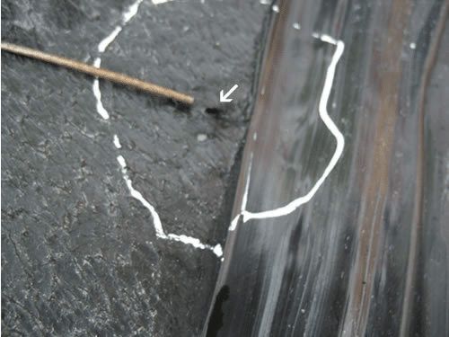
Figure 9. Small hole (arrowed) in liner next to weld. Rod is irrigation flag staff. Instead of a GCL a conductive geotextile could be used. But the simplest would be to use conductive sheet at sumps and penetrations. Since all welds are extrusion welds there is no concern about false positive signals at welds. Of course design engineers can help by avoiding pipe penetrations on shallower slopes where possible, and they can specify larger flange plates or boots to move boot skirt welds well down the slope from underneath the pipe. This should automatically be done by installers when field-fabricating boots. So, spark testing deserves more attention than it gets. Dr. Ian D. Peggs, P.E., PEng is President of I-CORP INTERNATIONAL,
Get Free Sample
We’ll respond as soon as possible(within 12 hours)