
+86-159 9860 6917
info@geofantex.com
geofantex@gmail.com
+86-400-8266163-44899
Looking to install a reinforced retaining wall? We specialise in such installations using Biaxial Geogrid
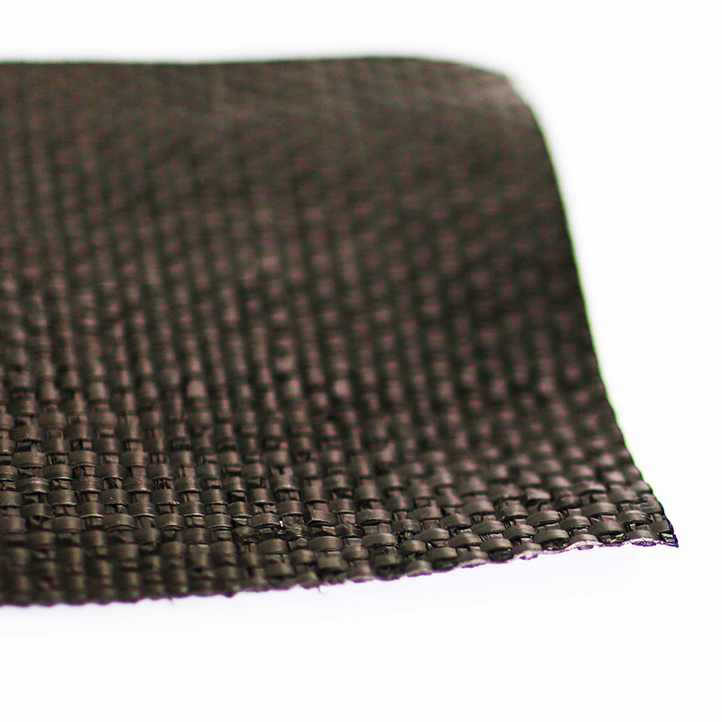
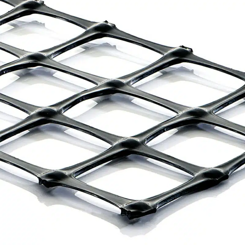
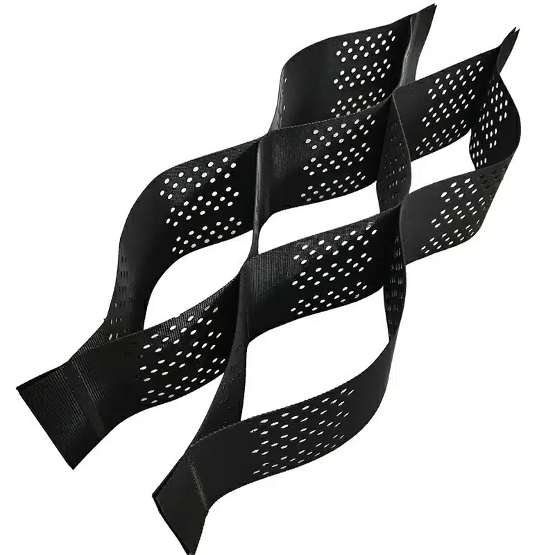
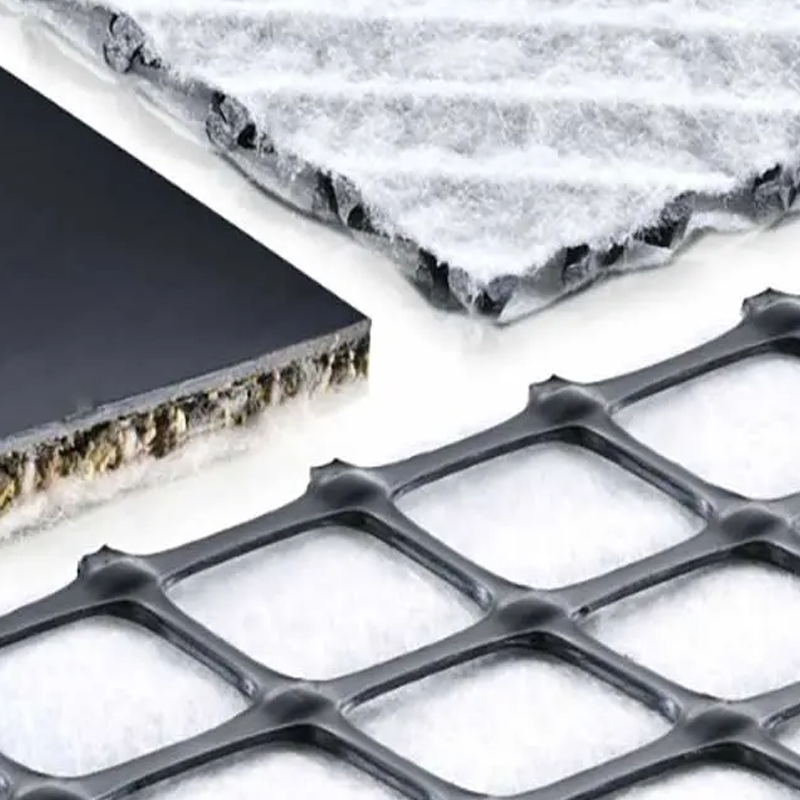
Biaxial Geogrid is an integrally formed structure, manufactured from Polypropylene. It has been specifically designed for soil stabilisation and reinforcement applications. More simply, geogrids can be described as largescale flexible, synthetic meshes that are specially manufactured for slope stabilisation and earth retention.
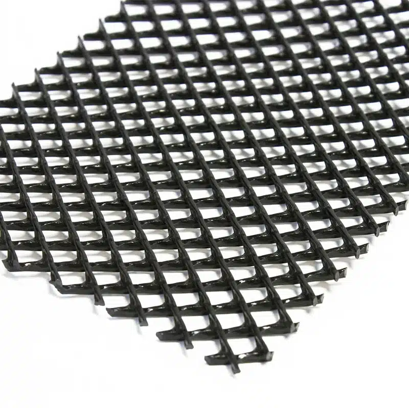
Biaxial Geogrids have square or rectangular openings which are also called apertures. This advanced type of geogrid is used for ground stabilisation across the globe and is popular in projects such as road stabilisation, reinforcing foundations, etc.
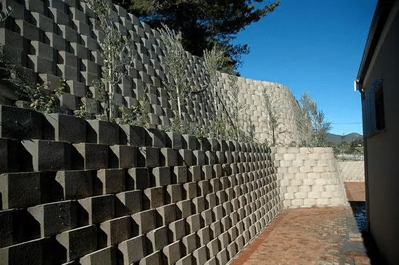
Retaining walls that rely solely on the weight of the retaining wall blocks to retain soil are often referred to as gravity walls. Some retaining structures, however, require support. This is often prevalent in retaining walls that exceed a certain height limit. Retaining wall structures can be reinforced with Geogrid which stabilises the soil and therefore prevents the retaining wall from collapsing under its own weight. Biaxial Geogrids feature high tensile strength in both longitudinal and transverse directions. With its excellent structure, stability and strong mechanical interlock performance, this product is ideal for soil reinforcement.
Decorton are the engineers’, architects’ and landscapers’ first choice when it comes to the design and installation of a diverse range of retaining requirements – be it for commercial, industrial or domestic purposes. To ensure that every installation done by our team is in line with our impeccable standards, we only make use of DRS Biaxial Geogrid GG2020 for the installation of any reinforced retaining wall. This product is specifically manufactured to be used for:
- Base reinforcement
- Subgrade reinforcement
- Slope reinforcement
- Embankment stabilisation
- Highway infrastructure
- Erosion control
- Landfill construction
About choosing the right reinforcement for your retaining wall…
To ensure stability and longevity, many retaining walls require that additional reinforcements be installed. These reinforcements are especially crucial to ensure that the retaining structure does not collapse during heavy rains. For the best results, our team makes use of high-quality Geogrid as part of our retaining wall installations.
Some considerations that need to be taken during the design and installation of geogrid for retaining purposes, include:
- Grid Strength – the right strength needs to be selected for the project, otherwise the embankment may start shifting over time.
- Installation length – the length of the grid should extend behind the wall to create sufficient stability.
- Total number of layers – enough layers should be added to increase the soil mass’s strength to handle the weight of applied loads.
- Spacing between layers – the grid layers should be spaced correctly and consistently to evenly distribute internal strength.
- Connection strength – retainer blocks and geogrid layers need to work in conjunction to resist natural forces.
During each of our projects, our experienced team take these factors into consideration to install a solid structure that will last for years to come. We also follow a strict installation procedure when constructing a reinforced retaining wall, assuring that our clients may enjoy complete peace of mind.
To discuss your options for the creation and installation of retaining walls using geogrid technology, do not hesitate to contact us.
Installation Guide for use of Geogrid in a Retaining Wall
Before placing geogrids, excavate to the lines and grades shown on the project grading plans and clear the ground surface of all debris or as directed by the design engineer.
- Install all materials at the proper elevations and orientations as shown on the construction plans or as directed by the project engineer. The segmental concrete retaining wall units and geogrid should be installed in strict accordance with the block manufacturer’s recommendations.
- There must be no overlap of the geogrid in the design strength direction (perpendicular to the wall face). Each length of geogrid must be one continuous piece of material.
- All geogrid should be installed under tension in the design strength direction. A nominal tension should be applied to the geogrid and maintained by staples, stakes, or hand tensioning until the geogrid has been covered by at least 6 inches of structural fill. Adjacent geogrid panels should be butted on one another to achieve 100% plan view coverage.
- Place the reinforced backfill in a maximum compacted lift thickness of 8 inches. Reinforced backfill should be compacted to a minimum of 95% of the standard Proctor density (ASTM D698) and at a moisture content within 2% of optimum or as required in the construction specifications or as directed by the project engineer. Only place the quantity of geogrid that can be backfilled on that day to limit damage to the installed geogrid.
- Backfill should be placed, spread and compacted in a manner that limits the development of wrinkles or movement of the geogrid and the segmental retaining wall facing units.
- Only walk-behind compaction equipment should be allowed within 5 feet of the back of the segmental retaining wall facing units.
- Tracked construction equipment should not be operated directly on the geogrid. A minimum backfill thickness of 8 inches is recommended prior to operation of tracked vehicles over the geogrid. Turning of tracked vehicles within the reinforced zone should be kept to a minimum to prevent displacing or damaging the geogrid.
- Rubber tire equipment may pass directly over the geogrid at slow speeds (less than 5 miles per hour). Sudden braking and sharp turning while passing directly over the geogrid should be avoided.
- All drainage fill and drainage medium materials should be placed in strict accordance with the construction plans or as directed by the project engineer.
- Drainage collection pipes should be installed to maintain gravity flow of water outside of and away from the reinforced zone as designed by the project engineer.
Get Free Sample
We’ll respond as soon as possible(within 12 hours)