+86-159 9860 6917
info@geofantex.com
geofantex@gmail.com
+86-400-8266163-44899
Geogrid segmental retaining wall is used where tall wall is required. Details and design of geogrid segmental retaining wall with calculations is described in this article. Segmental retaining wall height is restricted due to stability issues, but the height can be increased with the help of using woven synthetic sheet or in another term geogrids as successive layers at the back face of the wall. Layers are positioned and anchored into the facing blocks as shown in Figure-1 result in creating reinforced earth unit mass that acts against overturning and sliding actions. The geogrid segmental retaining walls can be constructed for height more than 12m. Different loads and reactions acted on the wall are shown in Figure-2.
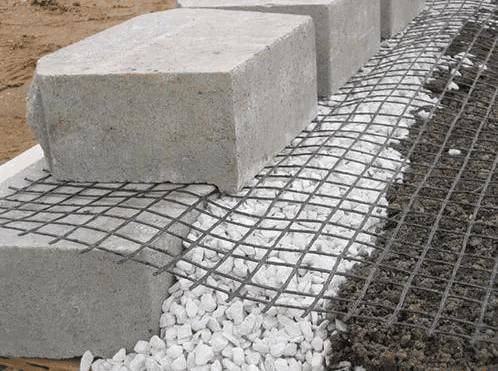
Figure-1: Geogrid anchored into the facing blocks

Figure-2: Loads and Forces acting on Geogrid Segmental Retaining Wall
There are various types of geogrids with different tensile strength that produced by manufacturers. Generally, Geogrids are 3.65 m wide and the length is depending on design requirements. Ultimate strength of geogrids is determined by test as per either ASTM or Geosynthetic Research Institute (GRI). Moreover, long term design strength is calculated from ultimate tensile strength by using a safety factor to take detrimental effects to considerations, such as long term degradation, damages during construction, material deficiency. Additionally, design safety factor 1.5 is used for Long Term Allowable Design Strength (LTADS) and it would be (LTADS/1.5). Geogrids are commonly anchored into the facing wall joints at one end and in-situ soil beyond the backfill to achieve effective utilization of geogrids. Resistance against pullout is consist of friction coefficient at block joint and any engagement technique that is employed for example pins through geogrid interstices, folding geogrids over a lip in the block as shown Figure-3 and Figure-4 in respectively.

Figure-3: Pin through geogrid interstice
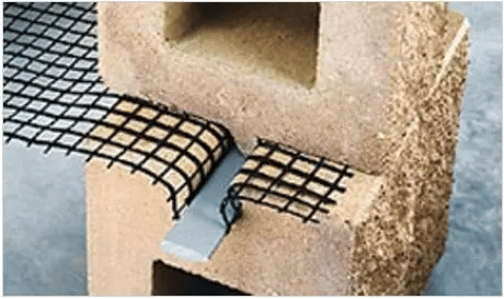
Figure-4: Engagement of geogrid by a lip of blocks
Blocks are tested to determine connection values for various types of geogrids. Ultimate connection value for blocks is computed as follow: Peak connection strength = 425 + 0.27N, with a maximum of 8.45 KN –> Equation-1 Where: 425: is the value of the proprietary geogrid engagement to the block 0.27: is the tangent of block-geogrid-block friction angle N: is the weight of overlaying blocks And safety factor of 1.5 is used for connections.
- Procedure for Design of Geogrid Segmental Retaining Wall
- Design Criteria for Geogrid Segmental Retaining Wall
- Masonry Units
- Calculation of Lateral Soil Pressure
- Coulomb Equation for Lateral Earth Pressure Calculation
- Selection of Geogrid for Segmental Retaining Wall
- Check Required Geogrid Length beyond Failure Plane:
- Determine Geogrid Embedment Length (Le)
- Retaining Wall Base Width Calculation
- Check for Overturning of Retaining Wall
- Sliding Check at Lowest Geogrid Layer
- Check for Soil Bearing Pressure
- Soil bearing capacity
Procedure for Design of Geogrid Segmental Retaining Wall
Design Criteria for Geogrid Segmental Retaining Wall
Determine retaining wall height along its length, plan view alignment, and contouring that sloped backfill may be needed. Moreover, find out characteristics of both in-situ and back fill soil which includes density and internal friction value (). Consultants provide values with necessary recommendations such as whether checking for global stability is needed or not and required values for internal friction and density. Backfill materials should be well drained and Unified Soil Classification System specify GW group for backfill material.
Masonry Units
Choose masonry units Based on specified size, texture, and configuration. Supplier proximity could play considerable role in determining block units.
Calculation of Lateral Soil Pressure
Coulomb equation is used to compute lateral earth pressure and it is recommended to find Ka factor for backfill soil which is reinforced by geogrid and the soil beyond the reinforce soil because properties like density and internal friction angle could be different. This means that internal force that is created by reinforced soil and external forces due to the soil beyond reinforced soil should be calculated separately. It is suggested that resultant forces act at an angle () therefore horizontal component is considered and vertical component is neglected.
Coulomb Equation for Lateral Earth Pressure Calculation

And Where: : Angle of internal friction : Angle of backfill slope : Angle of friction between soil and wall ((2/3) to (1/2) is assumed) : Wall slope angle from horizontal (90o+ batter angle from vertical)
Selection of Geogrid for Segmental Retaining Wall
Required tension resistance which depends on geogrid depth and vertical tributary area between layers, is used as a guidance to choose geogrid type and manufacturer. The first geogrid is poisoned in the first block joint then every two or three block another woven synthetic sheep is places but vertical spacing between geogrid layers should not be more than 60 cm. it is possible to use different spacing between geogrid layers depend on design requirements however equal spacing is used because of practicality. Moreover, internal earth pressure for each layer of geogrid is calculated upon specifying trial spacing. This force should be resisted by anchoring geogrid end into the facing blocks and another end into the backfill soil an adequate distance beyond failure plane.
Check Required Geogrid Length beyond Failure Plane:
This computation depends on frictional resistance along the geogrid, nature of geogrid surface, weight of overlying soil. Geogrid layer tension (Ta) increases with increasing its length anchored in the soil beyond failure plane: Where: Kaih: Horizontal component of Ka depends on Ka of internal (backfill) soil Z: Soil depth above geogrid layer : Soil density S: Tributary height to a layer, calculated as: The value of (Ta) horizontal geogrid tension per longitudinal meter of the wall and this value is used to determine long term allowable design strength of geogrid.
Determine Geogrid Embedment Length (Le)
Geogrid length embedded in the soil beyond failure plane should be enough to oppose pull out action. Pull out resistance is the combination of friction between soil and geogrid surface includes both top and bottom surfaces, weight of overlaying soil, and soil friction angle. Furthermore, reduction interaction coefficient (Ci), which based on geogrid and surrounding soil, is employed. Common value for Ci is between 0.70-0.90. Embedment length beyond failure plane is calculated as per the following equation in which additional soil in backfill soil and both dead and live loads are neglected: Where: Fs: Safety factor, minimum is 1.5 Kahi: Active pressure coefficient of internal soil (horizontal component) S: Tributary area between next lower and higher geogrid : Angle of internal friction of soil Ci: Geogrid-soil interaction coefficient
Retaining Wall Base Width Calculation
It composed of wall thickness and width of reinforced soil. Total base width should be checked even though it assumed to be 60-70% of the wall height in the beginning of the design. This check is based on the failure plane angle that extends from wall base and outline boundary beyond which geogrid must be extend for suitable embedment. The angle can be determined by either Coulomb or Rankine method. The former, which provide steeper angle and in return require shorter embedment length compare with the latter, is used as follow: Where: : coulomb failure plane, measured from horizontal : internal soil frictional angle : slope backfill if applicable : wall-soil interface friction angle (commonly 2/3 ) For specific failure angle and any height hx, distance from outside face of the wall to failure line intercept La is calculated as: Where: : Wall batter measured from horizontal t: Wall thickness
Check for Overturning of Retaining Wall
Coulomb equation is used for overturning calculations and in-situ soil density and phi value are employed. The total overturning moment (OTM) is computed as per the following equation: Where: : Density of backfill soil : Backfill soil friction angle H: Wall height DL: Dead load LL: Live load Resisting moment (RM) is calculated as follow: Where: W: Wall weight B: Total base : Angle of wall batter measured from vertical : slope of backfill Factor of safety >/= 1.5
Sliding Check at Lowest Geogrid Layer
Resistance against sliding at the lowest geogrid layer is provided by soil friction angle and block-join-block interface that is obtained from vendor equation and sliding reaction is lateral earth pressure.
Check for sliding at the base
Check for Soil Bearing Pressure
Meyerhof method is used to compute soil bearing pressure for segmental retaining wall. Rectangular pressure distribution is assumed under the base and vertical force spread over effective base uniformly. The effective base width is less than full base width by a distance equal to the two times the imposed load eccentricity on full base with. Where B is the total bearing width
Soil bearing capacity
Ultimate soil bearing capacity is computed by Terzaghi’s equation and the term by which the cohesion is considered is removed from the equation because it assumed to be zero: Where: : In-situ soil density d: bottom block embedment depth, m Be: Effective bearing with, calculate as per Equation-9 Nq, Ny: are non-dimensional coefficients, Table-1 providing Nq and Ny for common ranges of soil friction Table-1: Values for for different soil friction Read More: Segmental Retaining Wall – Types, Design and Advantages
Get Free Sample
We’ll respond as soon as possible(within 12 hours)